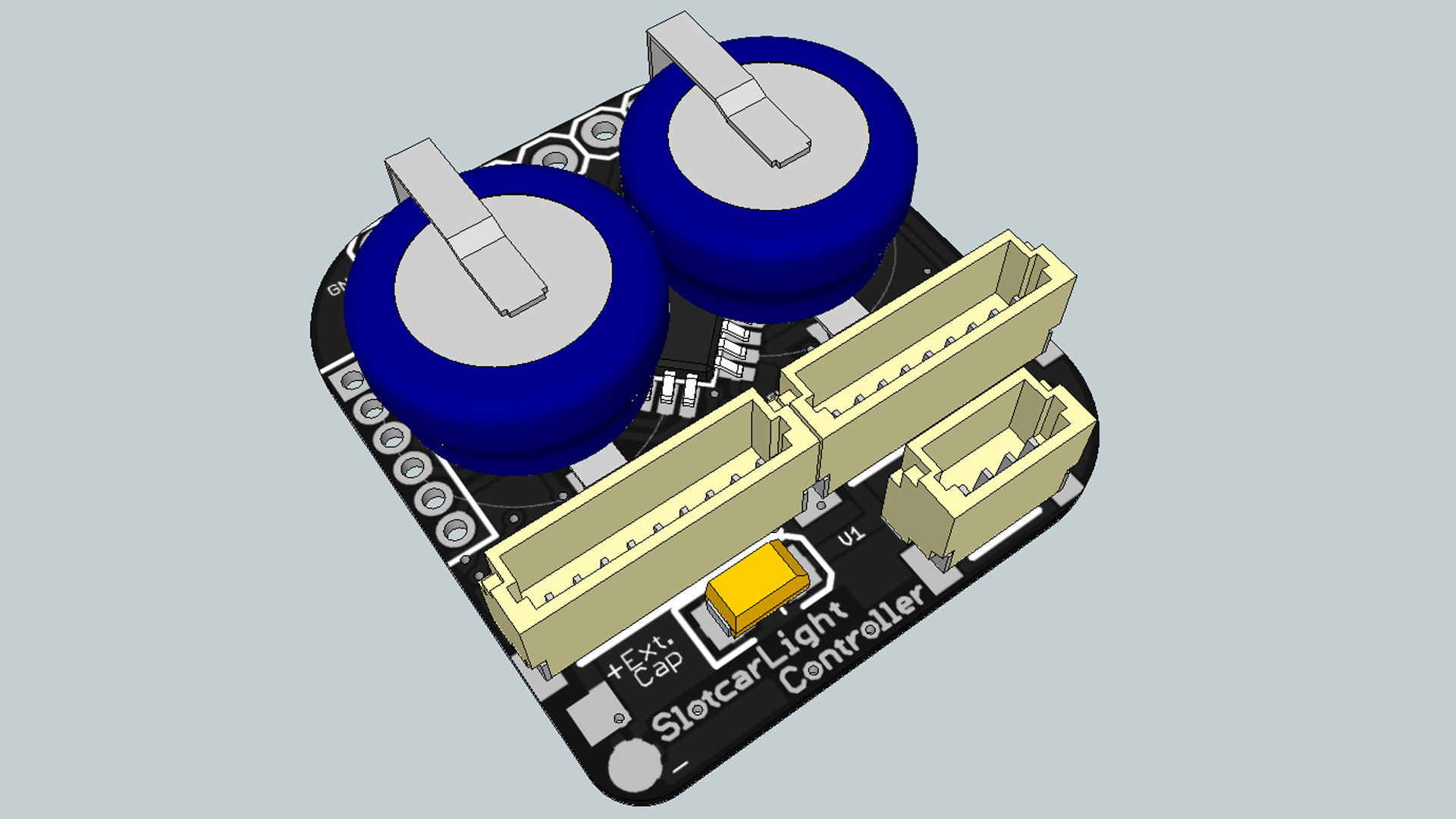
The SLC is a processor-based lightcontroller which allows the user maximum freedom for designing slotcar lights. The power buffering through two Goldcap capacitors (of 0.47 Farad each) guarantees a reliable power supply for the system. In that way the LEDs can give light permanently even when there are short time-outs from driving. The length of time for illumination can be prolonged by using a third Goldcap capacitor so that even vehicles with many LEDs can be powered optimally.
Fourteen channels are available on the SLC, all of which the user can adjust freely with the SLC Manager. Depending on the situation, LEDs can be turned on or off and they can be dimmed. Turn signals and chaser lights can be put together with as many channels as desired and their time intervals can be programmed without restrictions. Another option are random events, the parameters of which are defined by minimum and maximum values. By nature of the design an interference of the blinking LEDs with the permanently shining LEDs is precluded. Multiway connectors make an assembly of the SLC on the chassis possible so that body and chassis can be separated for easy maintenance.
At every start the SLC automatically calibrates itself anew in order to best display those light effects which were programmed with a voltage-dependent trigger. Every channel provides a voltage of 5 Volt, which means that—depending on the LEDs in play—the voltage has to be reduced through a dropping resistor. In the set included are resistors for the most common LED voltages (3.0 V white/blue (100 Ohm) and 2.0 V red/yellow/green (150 Ohm)). The strength of the afterglow of the SLC is directly related to the number of LEDs used.
Without a cooling element the SLC can be used with the following total loads depending on the input voltage: 6 Volt – 400 mA, 12 Volt – 150 mA, 18 Volt – 100 mA*. Please note that even without any LEDs attached the SLC has a power consumption of approximately 20 mA. The configuration at delivery has—if 18 LEDs are assembled—a power consumption between 80 and 120 mA.
With racetrack voltages of over 12 Volt we recommend that the enclosed cooling element be assembled.
* These values were determined on a workbench with continuous current. A change of voltage (e.g. when switching between driving and braking), cooling through airstream or glueing the SLC to a metal chassis will raise these values. Also, by dimming the LEDs the power consumption can be reduced.
In delivery status the SLC has a 14-channel programm:
1) The headlight flasher blinks in random intervals, as long as the handcontroller´s threshold value stays above 50% for 0 to 500 milliseconds.
2) The brake light comes on, as soon as the handcontroller´s threshold value falls below 1%. To improve the visibility of this effect, the brake light stays on for 200 milliseconds, even if the handcontroller´s threshold value goes higher than 1%.
3) The standard blinking pattern switches every 30 to 60 seconds for 5 to 10 seconds to a faster blinking pattern. These channels can be used as signal lights or overtaking blinklights for endurance races.
4) The exhaust flames start blinking during the brake phase for 250 to 1250 milliseconds. The delay makes sure that this effect is not seen during any brake phase.
5) The running light bounces in 1000 milliseconds.